There are 23 subjects, each subject video took around 75 mins to finish data extraction.
Feature extraction is performed using algorithm from Hamed.
Thursday, October 16, 2014
Wednesday, September 10, 2014
Data extraction
Data extraction
Procedures
- Perform OpenCv Haar Feature based Cascade classification on every frame of RGB video.
- Perform transforming/mapping for all frames of depth video. This should happen simultaneously with step one. After transforming, the depth pixels are relocated in same co-ordinates as RGB coordinates. Then we can get depth information of interested region from depth. The result image will be referred as "Mapped" in following context.
- For each area (left eye, right eye, mouth) detected in RGB frame , we can look up depth value for every pixel in "Mapped". And we stores the depth information of all area (eyes, mouth) in temporary images for later use.
- Resize temporary images to 36*24 for eyes, and 40*24 for mouth. (It is required for feature extraction and classification algorithm), and save all depth information in txt files.
Problem
The temporary image mentioned in step 3 was created as an Opencv Ipimage. The imageData of Ipimage is aligned in 4 bytes for better performance. For example, if we have a 50-by-50 (depth 8) image, and the imageData is aligned in 4 bytes. The size of reach row will not be (50*3 =150 bytes but 152 bytes i.e.152 % 4 = 0). It is dangerous to use pointer to manipulate the imageData, because there is no boundary check, and values from other memory address may be returned. However, it is fast to use pointer if we have hundreds of thousand pixels need to be processed.Tuesday, September 2, 2014
IR and RGB camera mapping
There are three coordinates system that relevant when we perform calibration, which are real world coordinates, camera matrices both IR camera and RGB camera.
Suppose P is a point in real world coordinates, P_ir (3D point) is the same point but in the perspective of IR camera coordinates, p_ir (2D point) is the same point in human perspective (the image). The relationship of P_ir and p_ir shows below:
$P_{ir} = {H_{ir}}^-1 p_{ir}$
$p_{ir} = {H_{ir}} P_{ir}$
Where H_ir is the intrinsic matrix of IR camera. which we obtain from previous calibration result.
P_ir can be transformed to RGB camera coordinates through the relative transformation R and T:
$P_{rgb} = R * P_{ir} + T$
Where R is the rotation matrix and T is the transition matrix.
Then we project P_rgb using H_rgb to obtain coordinates of P in RGB camera coordinates p_rgb.
$p_{rgb} = H_{rgb}P_{rgb}$
When two or more points projected on a same pixel, the closet point is chosen.
It should be noticed that both p_rgb and p_ir are homogenous coordinates, therefore when we trying to form p_ir, we need to multiply the pixel coordinate (x,y) by z, which is the depth value.
Find Rotation and Transition matrix
Extrinsic matrix transforms a point from 3D world coordinates to 3D camera coordinates.
The extrinsic matrices we are going to use are different in format from the ones in previous post. The extrinsic matrices are 4*4 in size, which consist a 3*3 rotation matrix (R) , a 3*1 transition matrix (T) and a row of redundancies. The extrinsic matrices are showing as following:
IR camera:
-0.026084 -0.928295 -0.370929 194.092830
-0.999637 0.021708 0.015968 51.210837
-0.006771 0.371211 -0.928524 278.779239
0.000000 0.000000 0.000000 1.000000
RGB camera:
-0.036546 -0.929878 -0.366048 185.288116
-0.998892 0.023121 0.040994 28.217325
-0.029656 0.367140 -0.929693 268.344275
0.000000 0.000000 0.000000 1.000000
Suppose a 3D world coordinate P, it can be transformed to a 3D camera matrix using the matrices above. The following relations can be found:
$P_{ir} = R_{ir}P+T_{ir}$
$P_{rgb} = R_{rgb}P+T_{ir}$
We substitute P in equation 2 with P_ir,R_ir and T_ir from equation 1, we obtain:
$R = R_{rgb}R_{ir}^-1$
$T = T_{rgb} - R_{rgb}R_{ir}^-1T_{ir} = T_{rgb} - RT_{ir}$
Applying data, the results are:
R:
[0.99993188 0.01050178 -0.00504891]
[-0.01061398 0.99968556 -0.02271776]
[ 0.00480963 0.02276964 0.9997292 ]
T:
[-7.92176365]
[-14.58407103]
[-12.45903772]
The result looks well. However, GML tool manual suggested that calibration with two patterns at same time will produce a much more accurate result. Because we are going perform Feature Extraction in pixel level, a more accurate calibration with two different patterns may be required.

Monday, September 1, 2014
RGB to Depth conversion
Basic information
Depth information captured from Kinect is stored in 16-bit data structure as shown below:| D13 | D12 | D11 | D10 | D9 | D8 | D7 | D6 | D5 | D4 | D3 | D2 | D1 | |||
| U3 | U2 | U1 | |||||||||||||
Real depth information
(13 bits)
|
User indicators (3 bits for 7 users)
|
||||||||||||||
Real depth information:13 lower bit indicate the distance between detected object and the Kinect depth sensor.
The accuracy of the IR sensor is 7 mm, therefore the first 3 lower bit are always zero
0
|
0 | 0 | D13 | D12 | D11 | D10 | D9 | D8 | D7 | D6 | D5 | D4 | 0 | 0 | 0 |
Real depth information (13 bits)
|
|||||||||||||||
RGB to depth conversion
In the sample video, the depth value is converted to 24-bit RGB value using Nui_ShortToQuad_Depth() from Kinect SDK, the following equations are used:
BYTE red= s;
BYTE green= s>>3 & 224;
BYTE blue3= s>>5 & 192;
Blue
|
Green | Red | |||||||||||||||||||||
| D13 | D12 | 0 | 0 | 0 | 0 | 0 | 0 | D11 | D10 | D9 | 0 | 0 | 0 | 0 | 0 | D8 | D7 | D6 | D5 | D4 | 0 | 0 | 0 |
In order to extract real value from the RGB representation, we need to do following mappings:
$Depth\;in\;mm=2^5 blue + 2^3 green + red$
Monday, May 26, 2014
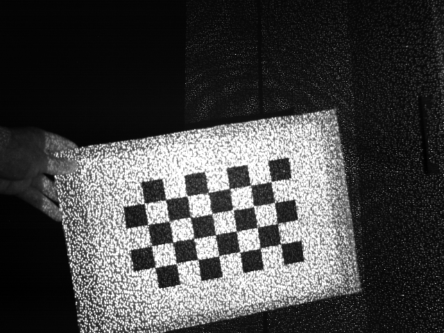
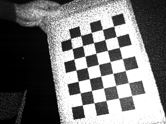
New chessboard pattern
New chessboard pattern had been applied. The pattern is 8*5 in size, and each block is 26 mm.
The two sets (RGB and IR) of pictures used for calibration are shown as following:
Once images were taken, I applied them separately in GML calibration tool. It gives intrinsic matrices, extrinsic matrices, and distortion parameters.


The extrinsic matrices for RGB camera is:
42.92 73.12 316.15 -2.00 2.06 0.42
63.21 -48.93 319.51 -0.02 3.03 0.24
57.10 -36.59 366.05 -0.06 2.51 -0.29
39.41 -72.19 361.86 0.63 2.60 -0.16
-31.39 -55.33 219.10 -1.73 -2.10 -0.78
42.52 15.09 495.30 0.25 3.07 -0.03
47.00 -92.77 482.56 1.44 2.23 -0.59
The intrinsic matrices for RGB camera is:
524.10 0 312.14
0 524.91 249.84
0 0 1

| 
|

| 
|

| 
|

| 
|

| 
|
| 
|

| 
|
The extrinsic matrices for RGB camera is:
42.92 73.12 316.15 -2.00 2.06 0.42
63.21 -48.93 319.51 -0.02 3.03 0.24
57.10 -36.59 366.05 -0.06 2.51 -0.29
39.41 -72.19 361.86 0.63 2.60 -0.16
-31.39 -55.33 219.10 -1.73 -2.10 -0.78
42.52 15.09 495.30 0.25 3.07 -0.03
47.00 -92.77 482.56 1.44 2.23 -0.59
The intrinsic matrices for RGB camera is:
524.10 0 312.14
0 524.91 249.84
0 0 1
The extrinsic matrices for IR camera is :
58.14 75.58 330.03 -1.99 2.04 0.40
80.93 -46.85 333.38 -0.03 3.00 0.26
72.56 -34.45 379.79 -0.05 2.48 -0.30
54.01 -68.20 381.87 0.63 2.56 -0.17
-12.85 -54.56 230.66 -1.74 -2.11 -0.80
54.45 16.40 518.28 0.25 3.02 0.02
57.72 -92.78 502.68 1.45 2.19 -0.57
The intrinsic matrices for RGB camera is:
612.32 0 326.70
0 614.54 242.53
0 0 1
Further calculation of mapping RGB to IR camera will be applied.
Saturday, May 24, 2014
Infra-red Image capturing
There are some existing applications such as Processing, MRPT which support IR Image capturing. However, they were all built for Xbox Kinect, and they does not support Kinect for Windows.
Furthermore, Kinect SDK does not provide a built-in IR image capture functionality, so I decided to use OpenCV, and OpenKinect (Libfreenect) to capture IR images.
OpenCV libraries are used for processing images. It is used in my application for creating/capturing frame from video, and saving the images.
OpenKinect libraries provide the drivers for Kinect in all system environment (Mac, Linux and Windows). And I used it for getting RGB video and IR video, then pass it to OpenCV to do further process.
Here are the images that I captured.(Left side was taken from RGB video, right side was taken from IR video):

| 
|

| 
|

| 
|
The calibration tool that I'm going to use is GML calibration toolbox.
The chessboard pattern I was using does not fulfil the requirements of the tool, it requires odd * even in size. New chessboard pattern will be applied.
Sunday, May 18, 2014
Kinect calibration Introduction
Kinect has two video cameras, one is for color image, another one is for Depth image. And two sensors are located geometrical differently,therefore, the colour image and depth image are not pixel-to-pixel synced for a same scene.
The sample data also contains a file of tracked points and its related Animation Unit. The tracked points data is recorded based on the coordinates of RGB video sensor, so in order to use these information for depth video, calibration is required.
There are varieties existing tools for calibration, all I need to do is to capture several pictures of a chessboard pattern from both RGB and IR cameras.
Friday, May 16, 2014
Procedures of the project
As I discussed with my supervisor, the project can be done in about 5 steps, as following:
1. Kinect device calibration.
2. Mapping RBG video to depth video or other way around.
3. LBP-TOP
4. Feature extractions.
5. Classification.
Thursday, March 27, 2014
Draft Proposal
Background
Video cameras are commonly integrated with variety devices for different proposes, thus, facial expression recognition (FER) becomes an important factor in HCI. FER is used in camera devices to capture the moment of smile, to recognising emotion for psychological studies etc.
Conventional web-cams or video cameras only function in the optimal light environment, therefore FER in non-optimal conditions is challenging us.
Xbox Kinect has a depth sensor, it consists an infrared laser projector and an infrared camera. The depth sensor works in any light conditions and it reflects the distance between camera and the object. By analyzing the video captured from depth sensor, we should be able to perform FER in any ambient light conditions. On the other hand, depth sensor from Kinect provides less human-recognisable image/video than RGB camera, thus it protects and ensures that the subject’s privacy is not being intruded.
Problem Statement
Address the difficulty of FER system working in non-optimal light condition and protect people’s anonymity by using Xbox Kinect depth sensor.
Methodologies
Feature extraction
Action Units(AU) are the fundamental actions of individual muscles. Different facial expression requires different combination of Action Units(AU). One approach is dividing facial image into several blocks, corresponded blocks will be detected and extracted for classification.
Classification
Machine learning algorithms will be used for classification. Training and testing data will be applied with 10-fold cross validation before classification.
Evaluation
Comparing the classification results with previous project which uses same video clips but in RGB color.
Subscribe to:
Posts (Atom)